Lux
HLD vs LLD in FTTH Design: What Each Stage Delivers

Written by
Lux Team
Category
Documentation
Date
Share this article
Two stages, two different questions
High-level design (HLD) answers whether and how to build. Low-level design (LLD) answers exactly what to build, where, and with which part. Mixing them up is one of the most common causes of rework on FTTH projects. One team draws pole-by-pole detail before the architecture is settled. Another starts construction from an HLD that was never meant to be built.
The HLD is a desktop exercise on GIS data:
address points;
a street centreline graph;
pole and duct layers where you have them;
aerial imagery.
It fixes the decisions that are expensive to change later:
serving area boundaries;
the central office or OLT location;
the split architecture and ratio;
hub or cabinet zones;
the feeder and distribution topology;
a first loss budget on the longest paths;
a cost per home passed that the business case can approve.
The LLD starts from that approved HLD and from field survey. It produces a design a crew can build and an inspector can permit. Every pole, span, duct, handhole, closure, splice and drop is specified, with lengths, fiber counts and part numbers.
The two stages also involve different people. HLD is usually owned by a planning or engineering lead working with the business case team. LLD involves survey crews, designers, make-ready engineers, permit coordinators and often a professional engineer who seals the prints. Each handoff between them is a chance to lose information.
Inputs a good HLD needs:
address points with unit counts, so multi-dwelling buildings are not counted as one home;
a routable street graph, not just a basemap;
pole locations and owners, even if heights and loading are unknown;
existing duct and any third-party fiber you can lease;
written design rules: split ratio, drop length limit, homes per terminal, spare policy and budget class;
a unit-cost rate card, so the cost per home passed means something.

What each stage delivers
Typical HLD deliverables:
serving area and cabinet zone map
architecture statement: centralized 1:32 or cascaded 1:4 × 1:8, budget class, spare policy
feeder and distribution routes, aerial vs underground split
terminal and splitter locations, homes per terminal
worst-path loss budget and a first check against design rules
high-level bill of materials and cost per home passed
early permit triggers: state highway, railroad and waterway crossings, which take the longest
Typical LLD deliverables:
construction prints by sheet, with pole-by-pole and span-by-span detail
exact cable routes, sheath sizes and fiber counts, slack loops and storage
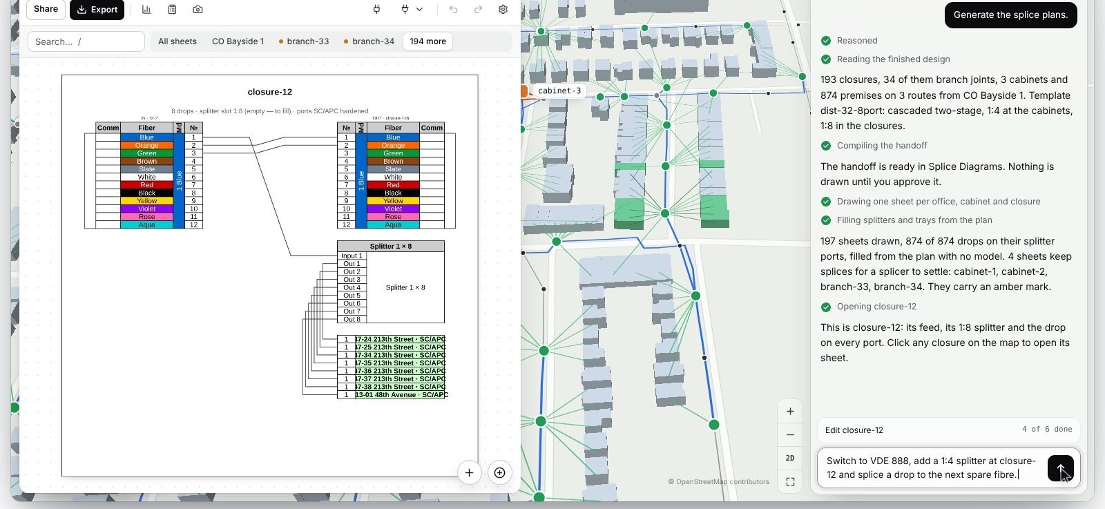
splice sheets per closure and cabinet: which tube and fiber goes to which splitter port or drop
conduit and handhole schedules, bore and trench details
make-ready and pole loading analysis for aerial routes
permit plan sets per jurisdiction
a detailed bill of quantities that a contractor can price
Ask vendors and consultants which of these they actually produce. "HLD" and "LLD" mean slightly different packages at different firms.
Timelines vary with size and data quality. Consultants commonly quote weeks for an HLD of a few thousand homes and several months for the LLD of the same area, because LLD waits on field survey, pole data and owner records. The slowest inputs are rarely the drawings themselves.
Agree on formats before the LLD starts. Permit offices often want PDF plan sets drawn from DXF or DWG. GIS teams want shapefile, GeoJSON or a geodatabase with attributes intact. Contractors want the bill of quantities in Excel, with one line per unit of work. If the design tool cannot produce these from one model, every format becomes a separate document someone has to keep in sync.
What changes between HLD and LLD
The HLD is built on desktop assumptions, and field survey corrects them. Expect these changes and plan for them:
Poles. A pole that looks usable in imagery is too short, too loaded, or owned by someone who will not allow attachment. This changes routes and can add make-ready. Our make-ready service covers that process.
Underground. Existing duct turns out to be full or collapsed. Surface types (asphalt, concrete, soil) change trench cost and permit type.
Demand. A multi-dwelling building has 24 units, not 4. A new subdivision appears. One terminal now overflows its homes-per-terminal limit.
Lengths. Routed lengths come out longer than the desktop estimate. That pushes drops past the length limit or the worst path past the loss budget.
Every one of these changes ripples downstream: routes, then lengths, then splice sheets, then the bill of quantities, then permits. The most useful property of a design process is not how fast it draws the first version. It is whether a change at one pole updates everything that depends on it, without someone redrawing three documents by hand.
Handoff checklist from HLD to LLD:
written design rules;
approved architecture and budget class;
a frozen serving area;
a list of known permit triggers;
a survey scope that names every pole and duct section the HLD assumed.
Common HLD mistakes that show up in LLD:
assuming every pole can take a new attachment;
sizing terminals on single-family homes and missing multi-dwelling units;
using straight-line distances for drop limits and loss budgets;
no spare fiber policy, so distribution cables are full on day one;
permit triggers found only when the plan set goes to the city.
Budget for this. A useful rule is to hold back part of the design effort for the changes survey will bring. Track them as changes to the approved HLD with a reason attached, such as pole rejected, duct blocked or demand added, so the business case can see why cost per home passed moved.
How Lux runs both stages
Lux treats HLD and LLD as one design that gets more detailed, not two separate files. The steps:
The agent proposes a plan: architecture template, counts and order of work. An engineer accepts it before drafting starts.
The agent places closures and cabinets.
It routes drops, distribution and feeder over the street and pole graph.
It checks the result against your rules, including length limits measured along the route and the loss budget on every path.
It prices the bill of materials and the bill of quantities from your rate card.
Approval is a recorded, versioned step that opens only when the checks pass.
From the approved design, Lux hands off to splice documentation: sheets per closure and cabinet that show feed fibers, splitters and drops, for an engineer to review. When as-built data comes back from the field, Lux records it on a separate branch, compares it with the design and re-runs the rules. A manager accepts the merge, and the bill of quantities is derived again from the result.
Designs export to DXF, shapefile, KML, GeoJSON and CSV for your CAD and GIS teams. See the design platform, our network design and splice and riser services, and GIS, CAD and as-builts for the records side.
The point is not to skip the engineering stages. HLD and LLD exist because the decisions in each need different evidence. The point is to stop retyping the same network into new files at each stage, and to keep one design of record that each stage refines.
Bring one serving area and see how a Lux design moves from plan to splice sheets with an engineer approving each step. Talk to the Lux team.
Frequently asked questions
What is HLD in fiber network design?
High-level design fixes the architecture of an FTTH network on desktop data: serving areas, OLT location, split architecture, cabinet zones, main routes, a first loss budget and a cost per home passed. It is the stage where the build is approved or rejected.
What is included in an FTTH LLD?
A low-level design contains everything needed to permit and build: construction prints, exact routes and fiber counts, splice sheets, conduit and handhole schedules, make-ready and pole loading results, permit plan sets and a detailed bill of quantities.
Does HLD include splice design?
Usually not. HLD sets splitter ratios and terminal locations; per-closure splice sheets belong to LLD, once routes and fiber counts are final.
Who approves an FTTH design?
The operator's engineering lead approves the HLD before LLD starts, and a qualified engineer reviews the LLD. Construction prints often need a professional engineer's seal, depending on the jurisdiction.
Share Blog